RF loopback — a design with a data converter
This is the worked example for the RF converter guide. It is the smallest graph that has a converter in it:
RfDataSource --RFSampIF--> Rfdc.rx_rf | Rfdc.rx_streams[0] --StreamIF--> RfSampPassThrough
                                                                                 |
RfDataSink   <--RFSampIF-- Rfdc.tx_rf | Rfdc.tx_streams[0] <--StreamIF-----------+
(rx_streams[0] because an Rfdc is a tile: one AXIS port per channel, and this graph has one
channel. RfLoopbackTB(n_ch=2) is the same five nodes with two ports per direction and two DUT
lanes — see the tile.)
Five nodes, four edges, and no signal processing anywhere. That is on purpose. Every other example in this collection is about what a kernel computes; this one is about the boundary the samples cross to reach a kernel at all — a boundary with its own clock, a granularity mismatch, and a failure mode that no protocol signal reports.
The two domains
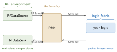
One Rfdc, used in both directions, and it belongs to neither box. On its left, blocks of
real-valued samples; on its right, packed integer words. The representation changes exactly there,
once in each direction — which is what makes a loopback a real test of it.
Pages
This example is a walkthrough in seven steps, split across three sittings:
| page | steps | what you get |
|---|---|---|
| Building it | 1–4 | the Rfdc, the source and sink, the four edges, and the DUT |
| Running it | 5–6 | what the gate claims, and two faults that make the counters mean something |
| Taking it to RTL | 7 | csynth, the XSI run, and the cycle gate |
Everything on the first two pages runs with no toolchain:
python -m examples.rf_loopback.rf_loopback
pytest tests/examples/test_rf_loopback.py tests/hw/test_rf_sample_if.py
Learning objectives
- Model an RF sample channel as an interface that owns a metronome — a clock, a block cadence, a buffer, and loss counters living on the edge rather than in a node.
- Model a data converter as a module carrying both directions, with
HwParamstructure (resolution, samples per word) separated from plain init-time knobs (the amplitude reference, the tile epochs). - Quantize bit-exactly with the integer-backed
FixedFieldand pack samples into stream words through the generated array serializers. - Assert a byte-identical loopback (shifted by the loop’s declared block latency) and that loss is exactly what the graph declared, and understand why the first check is not sufficient without the second.
- Read
check(mod, "xsi_bfm_model")as a finding about a module rather than a declaration on it.
Where the pieces live
| file | role | |
|---|---|---|
| the edge | waveflow/hw/rf_sample_if.py |
RFSampIF — framework, generic to any converter |
| the RF environment | waveflow/simulation/rf_tb.py |
RfDataSource / RfDataSink — framework, bundle-backed |
| the converter | waveflow/hw/rfdc.py |
Rfdc |
| logic + graph | examples/rf_loopback/rf_loopback.py |
RfSampPassThrough, RfLoopbackTB, RfLoopbackSim |
| the RTL build | examples/rf_loopback/rf_dut_build.py |
the DUT cut alone, between generic AXI-Stream BFMs |
| the figures | examples/rf_loopback/rf_loopback_figures.py |
every plot on these pages, rendered from a run |
The digital logic is synthesized and proved at RTL — cut alone, between generic
AXI-Stream BFMs. A page for the converter at RTL is not written: the models exist but nothing
wires them into a graph yet, so its rate conversions and counter-equivalence gate would be written
from the plan rather than from working code. See plans/adc_model.md.
See also
- RF converters — the concepts this example is written from.
- Free-running memory copy — the graph/procedure split and the bundle discipline this example reuses.
Table of contents
- Building it - Steps 1-4 of the walkthrough: create the converter and understand its parameter split, create the file-backed source and sink and choose a waveform, wire the four edges, and build the DUT as two tasks over an internal channel. Ends with a graph that runs — the checking is the next page.
- Running it - Steps 5-6: run the loopback and read what check() claims — byte-identical once shifted by the loop's declared block latency, loss exactly as declared, and alignment as a derived quantity. Then two deliberate faults, a late producer and a stalled consumer, that drive the counters off zero by predicted amounts, because a counter that has never counted is not evidence.
- Taking it to RTL - Step 7: the digital logic becomes hardware. What check says about each module in the graph, the DUT synthesized cut alone between generic AXI-Stream BFMs, one task body generated and one handed over, what each verification layer actually proves, and the recorded XSI cycle gate.