Building it
Steps 1 to 4. Nothing here needs a toolchain; at the end of step 4 you have a graph that will run.
python -m examples.rf_loopback.rf_loopback
1. Create the Rfdc
Rfdc models a simplified emulation of the
AMD RF Data Converter LogiCORE IP
— specifically, the interface your logic would see. Like the AMD block it exposes two AXI4-Stream
interfaces, one per direction, whose time origins can hold a fixed relation the way multi-tile
synchronisation does; its RF side simulates the signals the physical converter would emit or receive.
What Rfdc is, and what it is not has the full framing, including what the
model deliberately does not cover.
It is one module carrying both directions, not separate ADC and DAC blocks. The reason is synchronization: the TX and RX sample counters have to hold a fixed relation, and that is a property of the converter, not of two unrelated blocks — it is what lets the two grids’ time origins have a single owner.
rfdc = Rfdc(name="rfdc", sim=sim, word=Rfsoc4x2SampWord.specialize(samp_per_word=4),
            full_scale=1.0, t0_rx=0.0, t0_tx=blk_period)
Endpoints, in two pairs — one RF interface per direction, one AXIS port per channel:
| endpoint | type | direction |
|---|---|---|
rx_rf |
RFSampIFRx |
ADC path — RF blocks in from the environment, every channel in one block |
rx_stream_0 .. |
StreamIFMaster |
ADC path — AXI-Stream words out to the fabric, one port per channel |
tx_stream_0 .. |
StreamIFSlave |
DAC path — AXI-Stream words in from the fabric, one port per channel |
tx_rf |
RFSampIFTx |
DAC path — RF blocks out to the environment |
The two stream endpoints are the ones that would cross the cut in an RTL build; the two RF endpoints stay behavioural on both sides of it.
With the metronome living in the interface, the converter is reactive on the RF side: it has no timer of its own and simply responds to block arrivals.
The parameter split
| parameter | binding | why |
|---|---|---|
n_rx, n_tx |
HwParam |
RF channels per direction on the AXIS side |
word |
plain field, a type | the whole sample geometry — samples per beat, effective bits, container bits, iq_mode, and the two packing rules a serializer cannot know |
full_scale, t0_rx, t0_tx |
plain init-time fields | one artifact serves every value |
word is a plain field for a mechanical reason. HwModule.__post_init__ wraps every HwParam
value in HwParamValue(int(value)), so a type-valued parameter cannot be one. Nothing is lost: an
Rfdc declares no kernel_task, so none of its parameters ever reached a template argument — they
were build-time structure for the models, which read them off the word. See
what iq_mode means for real vs complex.
samp_rate is deliberately not on this list. It lives on the RF interface’s clock and the
converter reads it at bind; t0 travels the other way and is pushed. Two declarations that can
disagree is the bug both directions exist to avoid.
There is also no spc. word.samp_per_word is the structural integer; everything else at this
boundary is a rate ratio — derived, and generally fractional. The Python model needs neither
conversion, because it works in seconds.
full_scaleis not aDynParam, and the reason is worth knowing.DynParamdoes not mean “binds at init”; it means emitted as a member assignment —<model>.<field> = <expr>;. This value’s C++ realization is a constructor argument, riding inside theRfdcFormatliteral the generated models take, so tagging it would emit an assignment to a member that does not exist. Zero would be doubly wrong — meaningless as an amplitude reference and falsy, whichdiscover_dyn_paramsskips — so the constructor refuses it either way.
Bit-exact quantization
“Evaluate the effect of bit widths in Python” only means anything if the Python does what the
hardware will. So quantization is the integer-backed
FixedField — ap_fixed<bits_per_samp, 1> over [-1, 1), rounding and
saturating, because a converter clips rather than wraps — and sample↔word packing goes through
the generated array serializers, never a hand-rolled .range():
You do not write this — the Rfdc does it, on both paths. On the way in it quantizes each real
sample to a stored integer and packs samp_per_word of them into a beat; on the way out it unpacks
and dequantizes. Writing b for the word’s bits_per_samp — the effective width, never the
container — the arithmetic is:
stored = clamp( floor( x / full_scale * 2^(b-1) + 0.5 ),  -2^(b-1),  2^(b-1) - 1 )
    x' = stored / 2^(b-1) * full_scale
floor(· + 0.5) is round-half-up (AP_RND — not round-half-away-from-zero, which disagrees on
negative ties), and the clamp is the saturation (AP_SAT): a converter clips, it does not wrap. The
dequantization is exact, because the scale is a power of two.
At the 4x2’s 14 effective bits in a 16-bit slot, four to a beat, that is four samples per 64-bit
AXI-Stream beat — the effective width sets b above, the slot width sets the bus, and they are
two numbers. The gate runs
(8, 8), (16, 4), (12, 4) and (16, 2) — including a non-power-of-two width — because the bugs
hand-rolled packing produces hide at exactly the awkward widths.
2. Create the source and sink
Both are file-backed, and that is the discipline rather than a convenience: one on-disk bundle drives the Python run and, later, the RTL run, so the two backends can never start from different bytes.
self.source = RfDataSource(name="src", sim=sim, in_bundle="vectors/rf_in", start_delay=0.0)
self.sink = RfDataSink(name="sink", sim=sim, out_bundle="vectors/rf_out", depth=2)
write_scenario is the single scenario writer, and it is the only thing that produces input bytes.
Two waveforms, because they test different things
RfLoopbackSim(waveform=...) takes "grid" or "sine", and the difference is not cosmetic.
"grid" draws random samples exactly on the converter’s quantization grid —
m / 2^(bits_per_samp-1) · full_scale for integer m. A clean loopback is then bit-identical to the
input rather than close, which is what makes the packing check strict: a tolerance would hide a
packing bug, and packing is what this waveform exists to test. What it deliberately does not
test is quantization: on-grid samples make from_real a no-op, so rounding and saturation are never
exercised at all.
"sine" is a windowed sinusoid, and it exists to close exactly that gap. A sine does not land on
the grid, so from_real really rounds, and at 0.9 of full scale it is near enough the rail to
exercise saturation. The golden stays exact — no tolerance — it is just stated against the
quantized input:
assert np.array_equal(captured[k + n_lat], to_real(from_real(sent[k])))
That is the paragraph worth keeping: two waveforms, because one proves the packing is exact and the
other proves the quantizer is exercised at all, and neither substitutes for the other.
tests/examples/test_rf_loopback.py asserts the difference directly — the grid waveform survives a
round trip through from_real/to_real unchanged, and the sine does not.
The sine is also the one you can see. Here is what the source plays, read back out of the bundle it was written to:
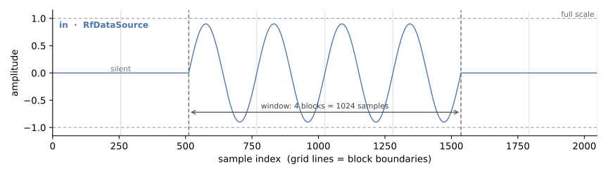
8 blocks of 256 samples, and the burst occupies the middle 4 of them — 1024 samples, silent either side. Deliberately away from block 0, so that the DAC’s startup zero-fill on the next page cannot be confused with the window simply being closed.
3. Wire the graph
Four edges, and only two kinds:
adc_if = RFSampIF(name="adc_if", sim=sim, samp_clk=self.samp_clk,
                  n_ch=1, blksize=256, n_blk=8)
adc_if.bind("tx", self.source.rf_ep)
adc_if.bind("rx", self.rfdc.rx_rf)
| edge | type | domain |
|---|---|---|
source → rfdc.rx_rf |
RFSampIF |
RF — blocks of real samples, on the sample clock |
rfdc.rx_streams[ch] → DUT |
StreamIF |
fabric — an ordinary AXI-Stream, one per channel |
DUT → rfdc.tx_streams[ch] |
StreamIF |
fabric — an ordinary AXI-Stream |
rfdc.tx_rf → sink |
RFSampIF |
RF |
Only the StreamIF pair would cross the cut in an RTL build; the RFSampIF pair stays behavioural
on both sides of it.
No depth= on the AXIS edges, and that is a correction rather than an omission. These become the
DUT’s top-level ports, and a top-level argument cannot carry a FIFO depth: Vitis ignores the pragma
(HLS 214-387) and the RTL gets the default of 2. composite_top_spec now refuses the declaration
outright — see the fidelity boundary.
Graph and procedure are separate objects
The same split as mem_copy: RfLoopbackTB.__post_init__ builds only
structure, because a component graph is data and can be walked, while a run-and-check function is
code and cannot. RfLoopbackSim owns the scenario, the run and the golden.
4. The DUT, and why it is two tasks
RfSampPassThrough is a FreeRunMod: one burst in, the same
burst out — as two tasks over an internal channel.
s_in --> [RfSampIngress] --blk_fifo (depth = nwords_blk)--> [RfSampBlockRelay] --> s_out
Free-running is the honest kind here — logic sitting between two converter ports has no host to start it and re-fires on each arriving block. The payload behaviour is trivial so that the loopback golden is exact rather than approximate: any difference between what went in and what came out is the plumbing, not an algorithm.
The structure is not trivial, and it is not decoration. It was one task — read a whole block, then write it — and that design dropped 72 of 512 samples at RTL. A converter cannot be back-pressured, so a stage that stops reading its input for 64 cycles at a stretch loses whatever arrives meanwhile. Splitting the read from the write is what lets block k+1 arrive while block k is going out — necessary, and not sufficient: it takes the loss to 62, not to zero, because the block stage still finishes a write before the next read and the DAC paces that write. See the RTL page’s correction. The structure below is still the right first move; what it does not do is make this design safe against a converter at both ends, which is what pattern B is for.
class RfSampIngress(FreeRunMod):        # never stops reading the boundary port
    def run_iter(self):
        words = yield from self.s_in.get()
        yield from self.w_out.write(words)


class RfSampBlockRelay(FreeRunMod):     # allowed to be busy: it holds a block
    def run_iter(self):
        blk = yield from self.blk_in.get_schema(self.blk_words)
        self.count_burst()
        yield from self.s_out.write(blk)
The channel between them is declared one block deep, and that declaration is honoured because the
channel is internal: #pragma HLS STREAM depth= works inside a top and is ignored on a top-level
argument. That asymmetry is why the elastic buffer has to be a task plus a channel rather than a
bigger number on the port.
The DUT declares what the loop costs
The DAC grid is a metronome, not a queue: it emits a block every period whether or not the samples for it have arrived. And DAC block k cannot carry ADC block k — the ADC only delivers block k at the instant the DAC period for it comes due, so the loop costs at least one block index however fast the fabric is. A zero-latency fabric would not close it either.
So the pipeline declares what it costs:
class RfSampPassThrough(FreeRunMod):
    blk_latency: HwParam[int] = 1      # >= 1 for any block-processing module
and blk_latency = 0 is refused at construction rather than reported later as a symptom — a loop
that claims to be free is not a slow system, it is not a system.
The testbench then sums the path: loop_blk_latency = 1 + dut.blk_latency, where the extra term is
the ADC’s own hop — a converter cannot emit samples it has not collected, so a block exists at
its grid tick and is transmitted across the following period. Two blocks in total, and that is the
number the next page checks against.
Two things this deliberately does not do. It does not stagger the tile epochs: t0_rx == t0_tx is
what MTS gives you, and buying pipeline latency by starting a tile late would model the thing MTS
exists to prevent. And it does not treat the resulting first-block underrun as a fault — a converter
fed by a pipeline must underrun until the data reaches it, which is exactly why a real design
primes its buffer before enabling the tile.
Next
- Running it — the three claims, and the two faults that make the counters mean something.
Source of truth: examples/rf_loopback/rf_loopback.py, waveflow/hw/rfdc.py,
tests/examples/test_rf_loopback.py.