Measuring a delay with an address
examples/rf_shot_loopback closes RfShotTx and
RfShotRx through one converter, with a path between them that
delays the samples, and both buffers built with
absolute_index = 1.
The result it exists for:
A sample sent from
mem[j]arrives atmem[(j + D) mod depth]. The channel delay is a difference of memory addresses — read off a window header and one sample value, with no timestamps, no correlator and no cross-spectrum.
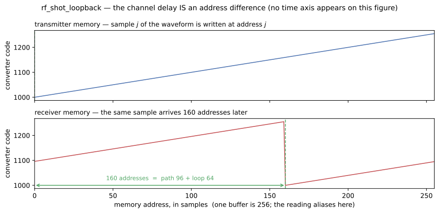
There is no time axis on that figure, and that is the point. Both panels are the same address axis,
one buffer wide: the waveform sits at address a on top and at a + 160 on the bottom, and the
160 is what the gate reads.
Read this first: it aliases at depth
The reading is a difference of addresses, so it is only ever known modulo one buffer. A path
delay of D and one of D + depth × samp_per_word produce the same number, and there is nothing
in the capture that could warn you.
So the geometry is chosen against the delay being measured. Here one buffer is 64 words = 256
samples and the demonstrated delay is 96 samples, comfortably inside it.
test_the_reading_aliases_at_one_buffer drives a path of 96 + 256 = 352 and asserts it reads 96 —
the rule’s other half, gated rather than left as a caveat.
What the two runs do differ in is how much silence arrives before the first sample: a longer path holds more of it. That is exactly the information an address discards and a timestamp keeps, and the same gate asserts it, so that the aliasing claim is not comparing a run with itself.
Why one converter carries both directions
Rfdc holds n_rx and n_tx in one module because “the TX and RX sample counters must hold a
fixed relation, and that is a property of the converter.” This is the first thing in the repo to
exercise that. Two converters would be two epochs, and a difference between addresses on two
unrelated counters would mean nothing at all.
One node sets t0 on every interface it binds, so the two grids share an origin structurally —
not because two testbench fields happen to agree. RFSampIF.set_t0 refuses a second, different
owner outright.
The three steps
1. Send a waveform and look at what comes out of the converter
The transmitter is loaded with a ramp of exactly one buffer — 256 distinguishable codes — and told
SHOT_LOOP, so it plays forever. Because it is built absolute, sample j of that waveform is
written at mem[j] and played there: the read pointer counts every word the design has emitted
since reset, so it is a timestamp rather than a position inside the current shot.
The waveform starts at a non-zero code (1000), and that is load-bearing.
FILLER is zero, so a waveform whose first sample were zero would
make the filler-to-signal transition ambiguous — in the playout log, in the figure, and in the
measurement itself, which skips filler because filler was never sent from an address.
What validates this step is the playout log, not a wall-clock: examples/rf_shot_tx’s gates
align on each backend’s own filler→play transitions rather than demanding the two agree about when
playing started. That is what makes the loosely-timed model usable here — the two backends disagree
about which pass a shot lands in and agree exactly about phase within the pass, and phase is what
this measurement uses.
2. Close the loop with a path that has a delay in it
Rfdc.tx_rf → RFSampIF → RfSampDelay → RFSampIF → Rfdc.rx_rf.
The delay is on a node, never on either edge. rf_sample_if’s own rule is “if the edge can only
record a quantity and never apply it, it does not belong on the edge”, and the reason it matters
here is the next section: a reader has to be able to tell a path delay from an epoch offset, which is
only possible if they are two different things.
It is a bulk delay, in whole samples, with no interpolation — a fractional delay is a filter, and
a filter would be a second signal-processing implementation nobody cross-checks. The demonstrated 96
is deliberately awkward: not a multiple of the 64-sample converter block and not a multiple of the
128-sample window, so a reading that came out right could not have come from a block index or a
window index. It is a multiple of samp_per_word, because an address is a word.
3. Capture it, and read the delay off the addresses
The receiver is absolute too, so it writes what arrives at mem[k mod depth] where k counts every
sample the converter has handed it since reset. Each announced window carries its base_addr, and
window_abs_index()
turns that into the window’s absolute position. Then, for every captured sample:
| question | answered by |
|---|---|
| which address was it sent from? | its code — the waveform is a ramp filling one buffer, so code - base is the address |
| which address did it arrive at? | window_abs_index(...) × samp_per_word + offset, from the header |
| the delay | the difference of the two, modulo one buffer |
Every one of 4576 captured samples returns the same difference. Unanimity is the assertion, not a side effect: a transmitter that slipped a pass, a receiver that mis-addressed one window, or a block lost anywhere on the loop each produce a capture that still looks like a waveform and still passes every counter — and each puts a second value in that histogram.
The number has two terms, and only one is the path
The raw reading is 160, and the path was configured with 96. The difference is not a fudge:
| term | samples | what it is |
|---|---|---|
| the path | 96 | RfSampDelay.delay_samp — what this example is measuring |
| the loop | 64 | one converter block, declared by the graph |
| raw address difference | 160 | what the capture carries |
A converter cannot emit samples it has not yet collected, so a block exists at its grid tick and is
transmitted across the following period. RfShotLoopbackTB.loop_blk_latency sums that hop with
what the nodes on the path declare — exactly as examples/rf_loopback does — and the measurement
subtracts it. It is declared, not fitted, and
test_the_loop_latency_is_declared_rather_than_fitted shows so by driving the path at zero: the
reading is then exactly 64.
An address cannot tell you why it moved
An RX address offset has two causes:
- a path delay — this path delivers later;
- an epoch offset —
t0on the converter, this tile’s counter started later.
test_an_epoch_offset_moves_the_reading_exactly_as_a_path_delay_does starts the transmit tile one
block late with the path untouched, and the reading moves by exactly one block: 160 → 224. The same
move a longer path would have made.
That is what MTS buys you. t0_tx ≡ t0_rx pins the epoch to zero so that what is left in the address
is the path — and Rfdc models a non-zero value as “a tile deliberately started late, or a measured
MTS residual”. This example sets both epochs explicitly rather than inheriting a default: an
assumption you cannot see in the graph is one you will forget you made.
The gate moves t0_tx and not t0_rx, and the asymmetry is a property of the model rather than a
preference. Starting the receive tile later can only cancel structural latency the loop already
has; past that a block simply waits in a queue. A gate that swept t0_rx would be asserting a
saturation curve rather than a correspondence.
Why the two loads are spaced
Under absolute indexing a playout is deferred to the next buffer boundary, and a load arriving
inside that window cancels the arm outright — and is still answered SHOT_LOADED. Nothing on the
command path can tell you; only the capture can.
examples/rf_shot_tx’s cmd_loop scenario is the demonstration: at absolute_index = 1 it plays
nothing at all. So this example separates its two loads with eight refused frames whose full
payloads have to drain, which is what buys the transmitter a whole pass of airtime in between. Four
is the measured threshold at this geometry; test_the_first_waveform_is_lost_when_the_loads_are_too_close
runs it at zero and two and asserts the first waveform never reaches the air while both commands are
still answered SHOT_LOADED.
Both waveforms then play, and the reading is unanimous across both of them — which is the part a single waveform could not show: the correspondence is a property of the addressing, not of one payload.
A third example, not a replacement
examples/rf_shot_tx and examples/rf_shot_rx stay, with their gate sets untouched. A loopback
cannot isolate a TX defect from an RX one — a wrong address here could be either end — so those two
remain the per-design contracts and this one adds only the pair’s claims:
- the address difference, and that it equals the configured delay;
- that it aliases at one buffer;
- that the two ends agree on one phase;
- that an epoch offset is indistinguishable from a path delay.
What is not built
There is no RTL rung. Both designs in this graph are synthesized and RTL-gated by their own
examples at this very absolute_index = 1 — 17 gates for the transmitter, 12 for the receiver.
Closing the loop at RTL would need a second locked memory inside one kernel and a C++ twin for the
path’s delay, and would re-derive a number two green gate sets already stand behind. The decision and
what it would take to change it are recorded in plans/rf_shot_absolute.md S3.
And a fractional delay is not modelled. The path shifts by whole samples. Interpolation is signal processing, and this example is about what an address means.
Next
- Running it — the build rungs and what each produces.
- Options and what is not built — the design space this example sits at one point of.
- Transmit —
RfShotTxand Receive —RfShotRx— the two halves.
Table of contents
- Running the loopback - The build rungs for rf_shot_loopback and what each produces: the SimPy run that measures the address difference, its aliasing and its epoch sensitivity and files the numbers as JSON, and the two on-demand figure rungs. No toolchain is needed for any of it, and none of the rungs synthesizes anything — the two designs in the graph are RTL-gated by their own examples.